Summary
By using this guide, each component on the machine can be identified, the parts that are prone to wear and their replacement times can be checked, and the installation data required for the workshop can be obtained before the production line arrives. All the following part numbers correspond to the disassembly diagrams in the corresponding chapters of the manual. The replacement cycle is based on normal operating conditions; when the machine operates in harsh environments, please shorten the replacement cycle.
All part numbers mentioned below refer to the exploded drawings of the corresponding chapters in the manual. Replacement intervals are based on normal operating conditions; shorten them when the machine runs in a harsh environment.
-
Structure & function
The 11 main assemblies of the machine - heater, rotary unit, transfer arm, mould support unit, distributors and more - with their working principles.
-
Vulnerable parts
Every wear part of each sub-assembly with its replacement interval, e.g. O-rings, springs and high-pressure valve repair kits.
-
Technical data
Capacity, bottle range, power, air and water consumption, plus the installation requirements for space, floor, environment and media quality.
XC8-00 Operation Manual - Structure & Technical Data
Download PDF · Chapter D-E · 6 MB
Equipment Structure & Function
The XC8 machine consists of 11 main assemblies. Each assembly is described below with its components, working principle and wear parts - click any assembly in the overview table to jump to its section.
Main assemblies overview
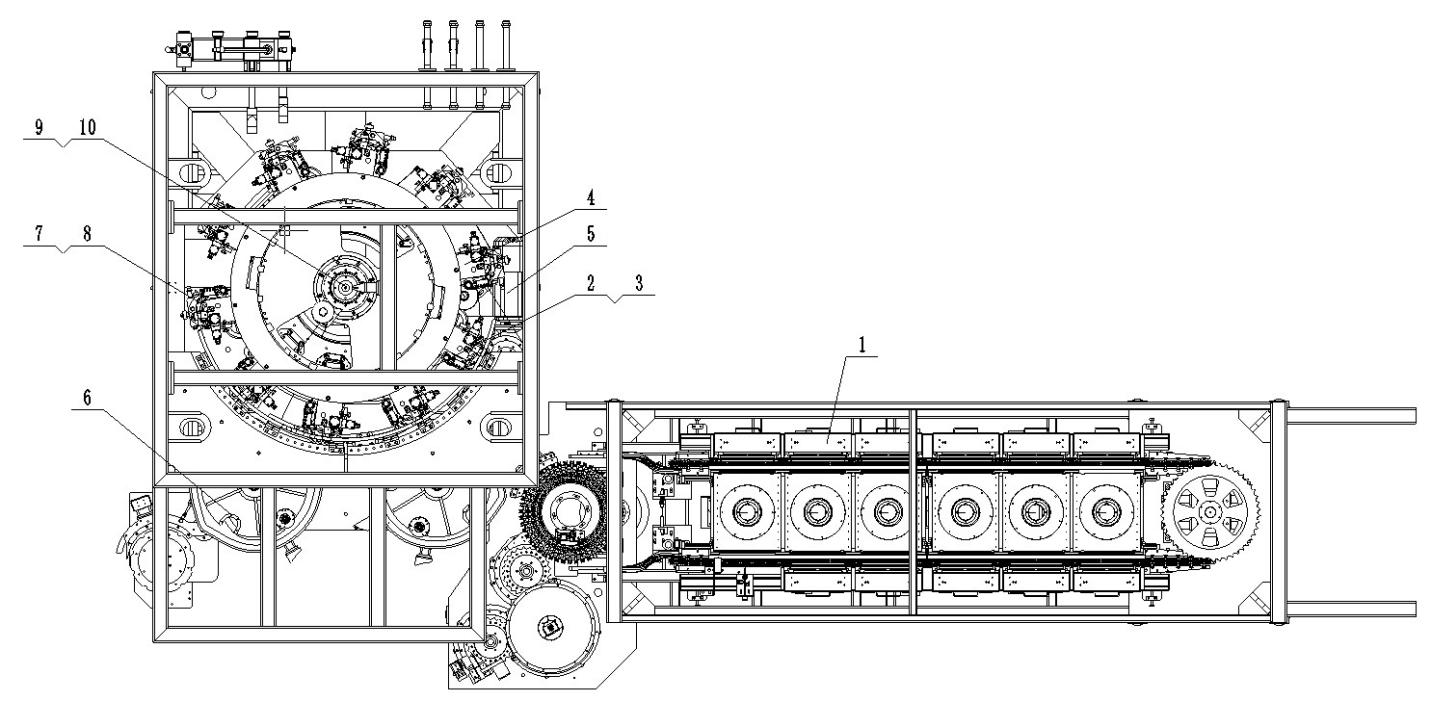
| No. | Assembly | Function |
|---|---|---|
| 1 | Heater | Infrared oven with 9 heating boxes; preforms self-rotate for even heating. |
| 2 | Mould opening / closing rail | Controls mould open / close positions, synchronous with preform feed and bottle discharge. |
| 3 | Driven system | Reducer motor, synchronous belts, brakes - the single power source of the machine. |
| 4 | Transfer system | Cam-driven robot arms that load preforms into the moulds and take bottles out. |
| 5 | Mould frame | Carries the bottle moulds: support unit, bottom mould lift, locking and compensation air. |
| 6 | Tensile mechanical sealing device | Stretching rod plus sealing cylinder: axial stretching, sealing and blowing. |
| 7 | Water distributor | Distributes mould cooling water to every station through the rotating body. |
| 8 | Air distributor module | Routes high / low pressure blowing air and control signals to the rotating stations. |
| 9 | Pneumatic line | Main air source, air treatment, filters and high-pressure valve groups. |
| 10 | Central lubrication layout | Programmed automatic greasing of rails, cams and bearings. |
| 11 | Control system | Electrical cabinet, PLC, touch screen HMI, wiring and sensors. |
1. Heater
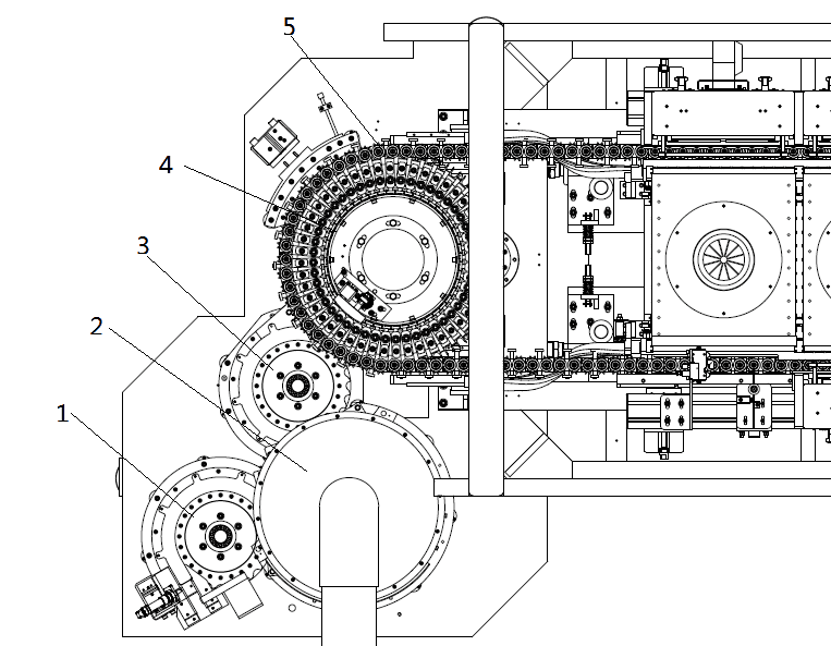
Preforms go from the preform-in module (1), preform-in dedusting starwheel (2) and preform-in transmission starwheel (3). Under the action of the heating top rail (4) each preform (5) is loaded onto a heating head. The preform then travels along the rail through several light boxes, and the heating head rotates it under the action of the self-rotation chain, so that the preform is heated evenly.
The heater is built from four modules: heating head, heating oven, drive module and deduster. Nine infrared boxes, each with individually controlled lamps, form multiple heating zones. PLC and HMI drive the power regulator for stepless adjustment of the lamp voltage, so the temperature profile of every preform section can be set precisely. Air fans overcome convection and stabilise the oven climate; air and water cooling prevent the bottle neck from being re-heated.
| # | Part | Function / remark | Service life |
|---|---|---|---|
| 1 | Heating head module | Expansion chuck holds the preform and rotates it through the oven. | - |
| 2 | Heating oven module | 9 boxes with multi-layer lamps, each layer controlled separately. | - |
| 3 | Drive module | Chain and sprockets, tension screws and rollers that move the heating heads. | - |
| 4 | Deduster device | Ionised air is blown into the preform to remove static dust; nozzle cleaned weekly. | Clean weekly |
| 5 | Bearing 9 + O-ring S3 | Wear parts of the heating head rotary unit. | 1 year / 5,000 h |
| 6 | Spring 13 | Chuck return spring inside the heating head. | 7,500 h |
Heating head. The expansion device (1), expansion device base (2), chuck (3) and preform unloading ring (4) are carried by the upper and lower sprocket assemblies (10, 11). When a preform passes a light box, the chain fixed on the heater frame meshes with the sprockets and the chuck rotates the preform for even heating. Two functions are handled by the top rails: the loading cam presses the expansion device into the preform, and the unloading cam lifts the unloading ring to release the heated preform onto the discharge starwheel.
Deduster. A positive / negative ion generator mixes ions with clean compressed air; the ionised air is injected into the preform through a nozzle. Static electricity on the preform wall is neutralised and the dust is blown out, then captured by the suction hood on both sides of the preform mouth and collected in a dust bag. Clean the nozzle weekly in normal conditions - daily in heavily polluted areas.
2. Mould opening / closing rail
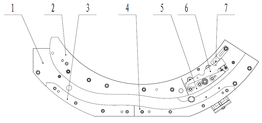
The rail controls the mould opening and closing positions and is synchronous with preform infeed and bottle discharge. Closing rail II (5) is a movable part: if a mould is not fully closed, the swing-arm bearing (A) pushes rail II aside, sensor (7) detects the signal and sends it to the PLC, which stops the machine immediately.
| # | Part | Function / remark | Service life |
|---|---|---|---|
| 1 | Rail seat | Fixed base that carries the rail segments on the mould base. | - |
| 2 | Mould opening rail | Opens the mould after blowing, in step with bottle discharge. | Lubricated by central system |
| 3 | Outer rail | Outer guide surface of the closing movement. | Lubricated by central system |
| 4 | Bushing / liner | Wear liner between the rail and its seat. | Inspect yearly |
| 5 | Mould closing rail II | Movable rail; pushed aside when a mould cannot close. | - |
| 6 / A | Swing-arm bearing | Rolls on the rail and pushes rail II on a closing fault. | Inspect yearly |
| 7 | Sensor | Detects the displaced rail and triggers the emergency stop. | - |
| 8 | Spring | Returns the movable rail to its working position. | - |
3. Driven system
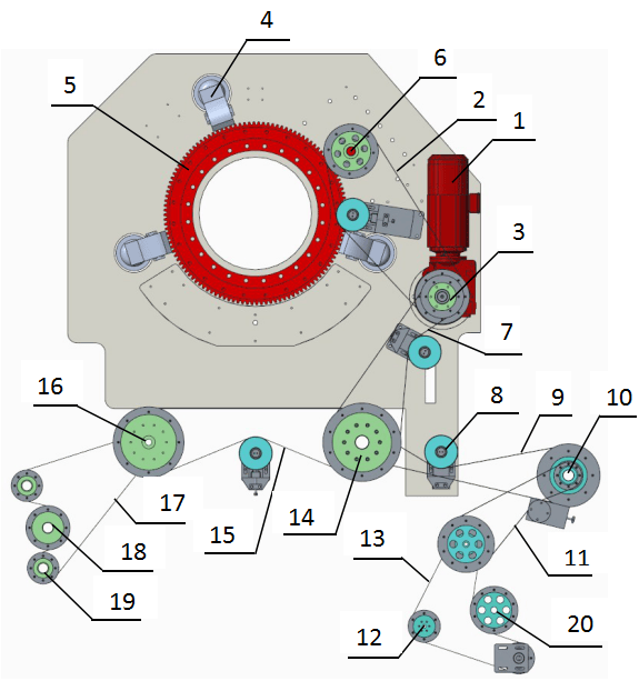
The driven system consists of the reducer motor, synchronous belts, pulleys, brake units and the slew bearing. The blow moulding machine is driven by one main motor through synchronous belt (A). The main motor is made of reducer (1), torque limiter (2) and pulley (3); the main drive consists of three air disc brakes (4), the drive gear (5) and pulley (6).
From the main drive, synchronous belts take power to the heater main drive (10), the preform infeed unit (12), the transfer arms (14, 16), the deduster (20) and the bottle discharge unit (19). Tension wheel seats (8, 11, 18) keep every belt at the correct tension.
When the motor is overloaded, the torque limiter slips; a micro switch reports the overload to the PLC, which applies the three air disc brakes and stops the machine.
| # | Part | Function / remark | Service life |
|---|---|---|---|
| 1 | Main motor + reducer | Single power source of the machine, speed controlled by the inverter. | - |
| 2 | Torque limiter | Slips on overload and signals the PLC through a micro switch. | Check yearly |
| 4 | Air disc brakes (3 pcs) | Brake and position the rotary unit when the machine stops. | Check pads yearly |
| 5 | Drive gear | Reinforced nylon gear driving the slew bearing; low noise, wear resistant. | Inspect backlash yearly |
| 6 | Slew bearing | Carries the rotary unit and transmits the drive torque. | Grease per plan |
| 8 / 11 / 18 | Tension wheel seats | Keep the drive, transfer arm and heater belts tensioned correctly. | Inspect monthly |
| 2 / 7 / 9 / 13 / 15 / 17 | Synchronous belts | Take power to the heater, transfer arms, infeed and discharge units. | Inspect monthly |
- Main motor speed is infinitely variable through the inverter.
- The whole machine has only one power source, which gives excellent synchronisation.
- All main transmissions use synchronous belts for accurate timing.
- The transmission gear is reinforced nylon: good damping and wear resistance.
Notes. (1) Add a suitable amount of grease to bearings and gears. (2) The contact pattern between the main drive gear and the slew bearing must be greater than 60%. (3) Minimum backlash between teeth: 0.2 - 0.3 mm.
4. Transfer system
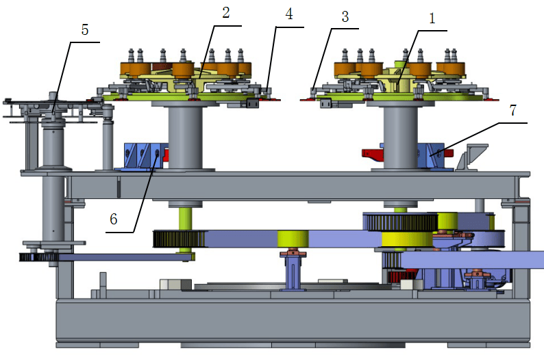
The transfer system uses a cam-linkage mechanism: simple in structure, well synchronised and coordinated. Every motion is controlled by electrical, pneumatic and rail elements, and the repeatedly optimised rail design guarantees synchronisation with the process and adaptability to the product.
Two turning wheels (2, 3) carry the arms: one takes preforms into the moulds, the other takes the blown bottles out of the moulds and hands them to the bottle discharge unit (5). The path of each arm is generated by a dedicated cam.
| # | Part | Function / remark | Service life |
|---|---|---|---|
| 1 | Preform feeding module | Picks the heated preform from the discharge starwheel. | - |
| 2 | Preform turning wheel | Carries the arms that load preforms into the moulds. | - |
| 3 | Bottle turning wheel | Carries the arms that remove blown bottles. | - |
| 4 | Transfer arm | Clamps neck and body; track generated by the cam. | Clamps: inspect yearly |
| 5 | Bottle discharge unit | Transfers the finished bottle to the conveyor. | - |
| 6 | Unlocking rail module | Releases the mould lock before the arms enter. | Lubricated by central system |
| 7 | Mould locking rail module | Locks the mould after preform loading. | Lubricated by central system |
Note. When the height of parts 1 and 2 has to be adjusted, tighten the hydraulic clamping sleeves with the special torque wrench at 40 N·m.
5. Mould frame
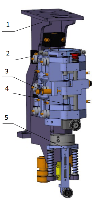
The mould frame carries the bottle moulds and consists of five groups: mould support unit (1), compensation air device (2), buffer device (3), mould locking mechanism (4) and bottom mould lift-down device (5).
Mould support unit. Supports the fixed and moving mould halves and the bottom mould bracket. The unit (1A) is mounted on the rotary bracket; shaft (4A) supports both mould halves; the swing arm shaft (3A) opens and closes the mould; buffer (2A) absorbs the closing impact; bearing (5A) runs along the mould opening / closing rail so that mould position, preform infeed and bottle discharge stay synchronous.
Bottom mould lift-down device. The locking device is mounted on the bracket and carries the bottom mould. Locking device (1B) allows a quick bottom mould changeover; rail (2B) and sliding block (3B) guide the up / down movement; spring (4B) buffers the rise; bearing (5B) rolls on the bottom mould cam so that the lift is synchronised with mould opening and closing.
Mould locking mechanism. After blowing, bearing (2C) follows the opening rail downwards, the stop block (1C) moves down, spring (5C) is compressed and the locking pin (4C) sits in the counterbore at the top of the slot - the mould is unlocked. When preform loading is complete, the stop block rises, spring (5C) returns, pin (4C) leaves the counterbore and the locking shaft (3C) moves up to clamp the mould.
Mould opening / closing. Bearing (7) follows the rail profile: the mould opens before bottle discharge and closes after preform loading. Connecting rods (4), linked by pins (3), open and close mould halves (1) and (2); the main link (5) drives the rods and both halves pivot on shaft (6).
Mould compensation air. Joint (4) connects the 40 bar air line. During blowing the high pressure presses the moving and fixed halves together, which reduces the parting line on the bottle. O-ring (3) seals the gap between the moving mould bracket (1) and the casing (2).
| # | Part | Function / remark | Service life |
|---|---|---|---|
| 1 | Mould support unit (1 / 1A) | Supports moving / fixed mould halves and the bottom mould bracket. | - |
| 2 | Bottom mould buffer spring (4B) | Buffers the bottom mould when it rises. | 1 year / 5,000 h |
| 3 | Locking spring (5C) | Returns the locking pin and clamps the mould. | 1 year / 5,000 h |
| 4 | Compensation O-ring (3) | Seals the 40 bar mould compensation air circuit. | Replace at once if damaged |
| 5 | Rail bearings (5A / 5B / 7) | Roll along the opening, bottom mould and closing rails. | Lubricated by central system |
6. Tensile mechanical sealing device
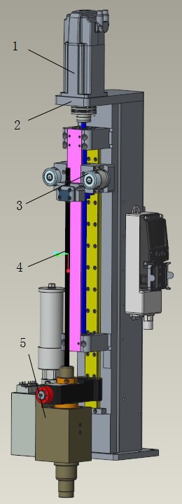
Mounted on the mould frame bracket are the stretching bracket (2), moving joint (3), stretching electric cylinder (1), stretching rod (4) and the sealing cylinder with high-pressure valve (5). After the preform enters the mould and the mould is locked, the stretching rod stretches the heated preform axially during pre-blowing while the sealing cylinder and high-pressure valve seal the mouth, admit pre-blow air (6 - 13 bar) and then the second blow (40 bar).
| # | Part | Function / remark | Service life |
|---|---|---|---|
| 01A | Shaft coupling | Links the electric cylinder to the ball screw. | Check every 6 months |
| 02A | Quick change device | Clamps the stretching rod for fast replacement. | - |
| 03A | Automatic single-point lubricator | Lubricates the ball screw. | Replace every 6 months |
| 04A | Ball screw | Moves the connecting block and drives the rod up / down. | Check every 6 months |
| 05A | Guide rail | Guides and supports the moving block. | Lubricated by central system |
| 06A | Bearing | Rolls on the mechanical sealing rail and gives the cylinder a stable upward force. | Inspect yearly |
| 07A | Driver | Receives the control signal from the main cabinet and switches the electric cylinder. | - |
| 5 | Sealing cylinder + HP valve | Seals the neck, pre-blow and second blow; grease every 6 months. | Seals: 1 year |
Electric cylinder maintenance. The cylinder drives the stretching rod, so it must be serviced regularly to keep the machine in good condition: check that it runs correctly every 30 days, and check wear of the coupling, ball screw and bracket every 6 months or every overhaul interval (the interval depends on the working environment). Electrical repairs should be returned to the cylinder manufacturer.
- Disconnect the power supply, then remove the electrical connectors.
- Separate the cylinder from the frame and store it in a clean, dry and safe place.
- Dismantle the mounting parts; check all non-electrical parts for damage and remove grease with a clean cotton cloth.
- Fit new parts, apply the specified grease evenly, reassemble and run the cylinder back and forth several times to check operation.
7. Water distributor
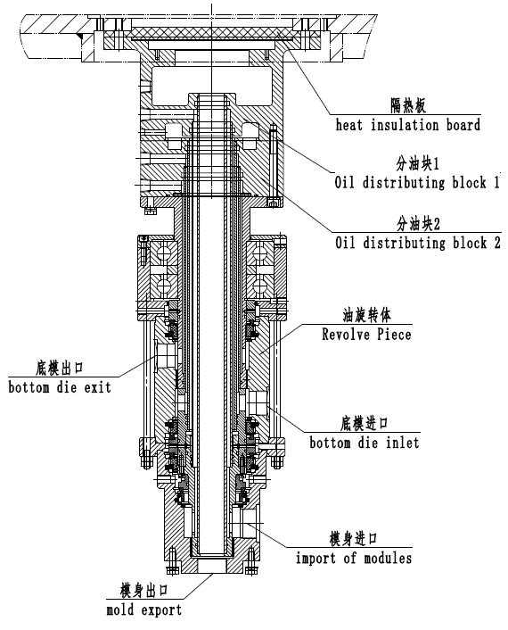
The water distributor (called oil distributor in the manual) supplies cooling water to every mould. It is made of a heat insulation board, water distributing block 1, water distributing block 2 and a rotating body. The insulation board stops heat from the distributor reaching the machine frame; the two distributing blocks split the water flow between the moulds; the lower part of the rotating body is static while the upper part turns with the machine.
Seals are mechanical seals. Under normal conditions they do not need scheduled replacement - only renew them when a leak appears at a joint.
| # | Part | Function / remark | Service life |
|---|---|---|---|
| 1 | Heat insulation board | Keeps distributor heat away from the machine frame. | - |
| 2 | Distributing block 1 / 2 | Split the cooling water to every mould circuit. | - |
| 3 | Rotating body | Lower part static, upper part rotates with the machine. | - |
| 4 | Mechanical seal set | Seals between the static and rotating parts. | Replace when leaking |
| 5 | Inlet / outlet sleeves | Feed and return connections of the mould circuits. | - |
Seal replacement. If water leaks at a joint, remove the two hex screws shown in the manual, take off the distributor and renew the seals one by one. For the rotating body: remove the five nuts, replace the seals in the inlet sleeve, take out TZMY16M-09 / TZMY16M-14 (fit new ones), remove the six M6 screws and pull off the tubes, renew the remaining seals, remove the set screw TZMY16M-03 and TZMY16M-08, take out the rotary sleeve, renew its seals and finally refit TZMY16M-02 with new seals.
8. Air distributor module
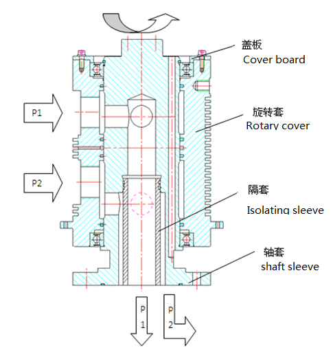
The air distributor supplies high-pressure air for the second blow (28 - 40 bar). The pressure is reduced to 6 - 13 bar and stored in the air tank, which feeds pre-blowing with a stable pressure and flow. The unit sits in the centre of the machine: because air is clean compared with oil and water, it is placed above the mould frame and the water distributor, with a support plate between them.
The distributor body consists of bushings, spacers, rotating sleeve and cover plates. O-rings seal between bushing and spacer, S-type roto glyd rings seal between bushing and rotating sleeve. The bushing rotates with the machine while the rotating sleeve is held by the support bracket; bearings centre the two parts. P1 is the high-pressure inlet and P2 the low-pressure inlet; both feed distributing block 1 and block 2 through internal passages.
| # | Part | Function / remark | Service life |
|---|---|---|---|
| 1 | Conductive slip ring | Transmits control signals to the rotating electrical components. | - |
| 2 | Distributor body | Two air passages for high and low pressure air (P1 / P2). | Seals: replace when leaking |
| 3 | Distributing block 1 | Feeds high-pressure and compensation valves of every mould. | - |
| 4 | Distributing block 2 | Feeds low-pressure air to stretching cylinders and pilot valves. | - |
| 5 | Air tank + relief valve | Stores low-pressure blowing air and limits the maximum pressure. | - |
| 6 | Encoder | Tracks every mould station and synchronises the actuator sequence. | - |
| 7 | Support plate / bracket | Carry the air and water distributors and keep the body from rotating. | - |
Seal replacement. Before any work: switch off power, air and water and make sure the machine is braked. Disconnect the terminals of the two wires on the slip ring (about 10 cores) and wind them around the ring; remove the stopper (3) with a 5 mm Allen key, the cover (2) with a 6 mm key, then the connecting seat (1) with a 5 mm key. Release the M16 nut and bolt of the support bracket, remove the encoder from rotary block 2, loosen the eight M10 nuts on the bushing flange and lift off the whole distributor body together with spacer (4) and O-ring. Open the cover (3), remove the circlip and pull out the rotating sleeve with its two bearings and four roto glyd rings.
Roto glyd ring installation. Deburr and chamfer all edges, clean every part, then bend the S-type ring into a "U" shape without sharp bends, press it into the groove against the O-ring and finally insert the shaft to restore the ring. Use only grease without solid additives (no molybdenum disulphide or zinc sulphide). Assembly follows the disassembly sequence in reverse; after assembly turn the sleeve by hand - the torque must be smooth, otherwise reassemble.
9. Pneumatic line
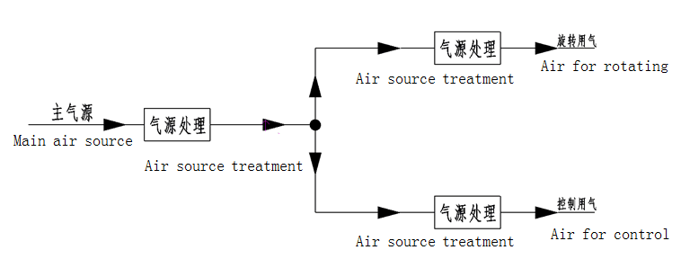
The air used on the machine is divided into blowing air and control air. Blowing air forms the bottle; control air drives pneumatic components and actuators such as high-pressure valves and cylinders. Both branches come from the main air source, which must pass through the air treatment unit for cleaning and filtration before use.
Blowing air is split into pre-blow (low pressure, 6 - 13 bar) and second blow (high pressure, 28 - 40 bar). Low-pressure air is stored in the air tank to give a stable flow and pressure for pre-blowing; high-pressure air completes the final blow.
| # | Part | Function / remark | Service life |
|---|---|---|---|
| 1 | Air treatment unit | Filters and regulates the main air source before it is split. | Drain daily |
| 2 | Filter element | Removes fine dust; unscrew the bowl, clean it and fit a new element. | 1 year |
| 3 | Sealing cylinder | Seals the bottle mouth during blowing; grease sliding parts every 6 months. | Seals: 1 year |
| 4 | High-pressure valve group | Switches pre-blow and second blow; flow control valve sets pre-blow flow. | Repair kit per plan |
| 5 | Solenoid valve module | Pilot control of the sealing cylinder. | - |
| 6 | Recovery valve | Recovers blowing air after the bottle is formed. | Inspect yearly |
| 7 | Muffler / adaptor | Silences exhaust and connects the valve group to the distributor. | - |
High-pressure valve group. Six parts: sealing cylinder, high-pressure valve group, sealing cylinder solenoid valve module, recovery valve, muffler and transition joints. The sealing cylinder, high-pressure valve group and recovery valve are integrated; the high-pressure valve controls high and low pressure air and the flow control valve regulates pre-blow flow. All joints are sealed with O-rings.
Before opening a valve group: close all air sources including P1, P2 and PAS, discharge the air in the system and cut off the valve power supply. Renew the cylinder seals after one year to prevent leakage.
10. Central lubrication layout
The central lubrication system greases on a programmed timer, which prevents damage to bearings and guide rails and keeps lubrication reliable. Lubrication points are the mould opening / closing rail, the bottom mould rail, the right cam and the left cam.
Single-point automatic lubricators feed the mechanical sealing rail, unlocking rail, heater deduster, heater top rail, turnover rail and the heater inner / outer rails; these units are replaced every six months.
- After assembly, fill the tubing with grease and bleed the air before connecting it to the oil inlets.
- Fill the pump with Shell Alvania EP2 grease.
- Set the single-point lubricators to six months after installation and commissioning on site.
| # | Lubrication point | Supply | Service life |
|---|---|---|---|
| 1 | Mould opening / closing rail | Central pump | Programmed |
| 2 | Bottom mould rail | Central pump | Programmed |
| 3 | Right cam / left cam | Central pump | Programmed |
| 4 | Mechanical sealing rail | Single-point lubricator | Replace every 6 months |
| 5 | Unlocking rail, turnover rail | Single-point lubricator | Replace every 6 months |
| 6 | Heater top / inner / outer rail, deduster | Single-point lubricator | Replace every 6 months |
11. Control system
The control system consists of the electrical control cabinet, the operating system, the wiring and the measuring and sensing elements. It controls the running of the whole machine and the manufacturing process.
The electrical control cabinet is the basis of machine operation; the PLC runs the control program. The operator station is a touch screen that starts and stops the machine, displays operating conditions and parameters, allows parameter changes, shows faults with an alarm and automatic stop, and records / queries production data.
| # | Part | Function / remark | Service life |
|---|---|---|---|
| 1 | Electrical control cabinet | Houses the PLC, drives and power distribution; keep the fans and filters clean. | Clean filters every 3 months |
| 2 | PLC + program | Runs the machine sequence and all interlock / safety logic. | Back up the program yearly |
| 3 | Touch screen HMI | Capacity, frequency and temperature display; parameter setting; fault alarm and record. | - |
| 4 | Wiring and terminal blocks | Power and signal connections between cabinet, sensors and actuators. | Check tightness yearly |
| 5 | Sensors / encoders | Mould position, rail safety, temperature and pressure feedback. | Inspect yearly |
Parameters shown on the HMI: output (bottles per hour), machine frequency, heating zone temperatures, blowing pressures and active alarms. Fault messages are logged with a time stamp so the maintenance team can trace repeated stops.
Technical Data
Basic parameters of the XC8-00 blow moulding line and the installation requirements for space, floor, environment, compressed air and cooling water. Final data always refer to the nameplate of your machine.
Basic technical parameters
| Item | XC8-00 |
|---|---|
| Capacity | 19,200 BPH |
| Bottle volume | 0.25 - 2.5 L |
| Max. bottle diameter / diagonal | 115 mm |
| Max. bottle height | 340 mm |
| Preform material | PET |
| Preform internal diameter | Φ14 - Φ26 mm |
| Preform height | 150 mm |
| Supporting ring diameter | ≤ Φ36 mm |
| Cavity number | 8 |
| Main driven motor power | 7.5 kW |
| Voltage / frequency / phase | 380V±10% / 50Hz / three phase + grounding wire |
| Heating oven quantity | 9 |
| Lamp quantity of each oven | 9 rows |
| Lamp power | 3 / 2.5 kW |
| Installation power | 285 kW |
| High pressure compressed air | 3.5 MPa, food-grade pure gas (clean, dry, oil free) |
| Cooling water pressure | 6 ± 0.5 bar |
| Cooling water - blow molder | 5 m³/h (water temperature 20 - 40 °C) |
| Cooling water - heater | 2.5 m³/h (7 - 12 °C) / 2.5 m³/h (17 - 22 °C) |
| Machine weight | Blow molder 14 t + heater 4 t |
Installation & environment requirements
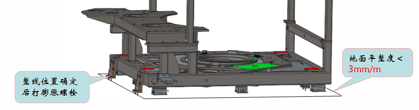
- Minimum working and maintenance space: footprint 12 × 9 m, height 5 m (excluding transport and lifting space).
- Floor: C30 steel-reinforced concrete, 300 mm thick; epoxy resin floor paint, floor drains at the lowest points.
- Temperature 24 ± 2 °C (min 15 °C, max 35 °C); humidity 60 - 70%.
- Air cleanliness class 100,000; dust-free, mould-proof, moisture-proof and shock-proof blowing room with fresh-air filtration.
- Install proper ventilation above the heating oven to keep the thermal balance of the system.
- Blowing room door: curtain or air curtain to separate from other rooms; wall tiles up to 1.2 m; lighting approx. 300 W per 6 × 6 m.
Compressed air & cooling water quality
Compressed air piping must be purged clean for at least 2 hours before connection and use stainless seamless steel pipes; pressure fluctuation ≤ ±0.1 MPa; a terminal filter is recommended at the machine air inlet (GB/T 13277.1-2008).
| Substance in compressed air | Class | Max. value |
|---|---|---|
| Solid particles | ≤ 1 | 0.1 μm / 0.1 mg/m³ |
| Water | ≤ 4 | Pressure dew point 3 °C |
| Oil | ≤ 1 | 0.01 mg/m³ |
| Cooling water item | Requirement |
|---|---|
| Water standard | Drinkable water standard, no impurity / pollution, reusable |
| PH value | 7 - 8 |
| Carbonate hardness (CaCO₃) | < 140 mg/L |
| Mechanical impurity | None |
| Pollutant particle size | ≤ 0.1 mm |
| Additive | Suitable antifreeze / preservatives |